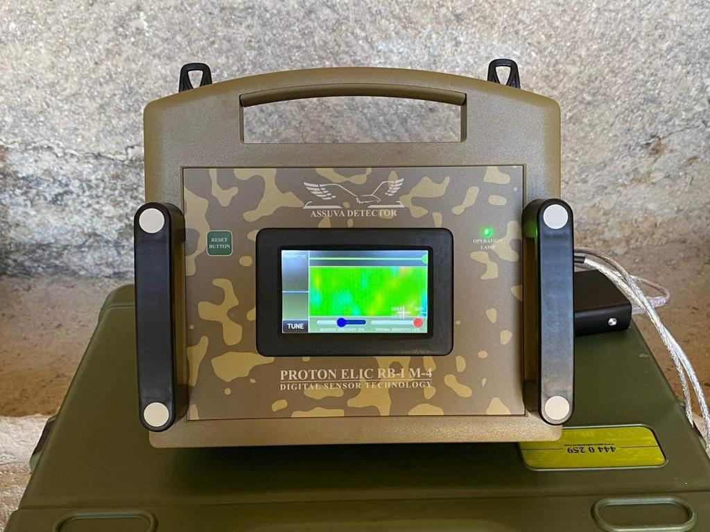
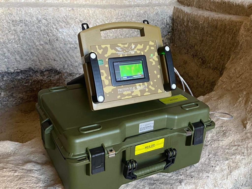
PROTON ELIC RB-I M-4 PROFESSIONAL IT’S A MONSTER
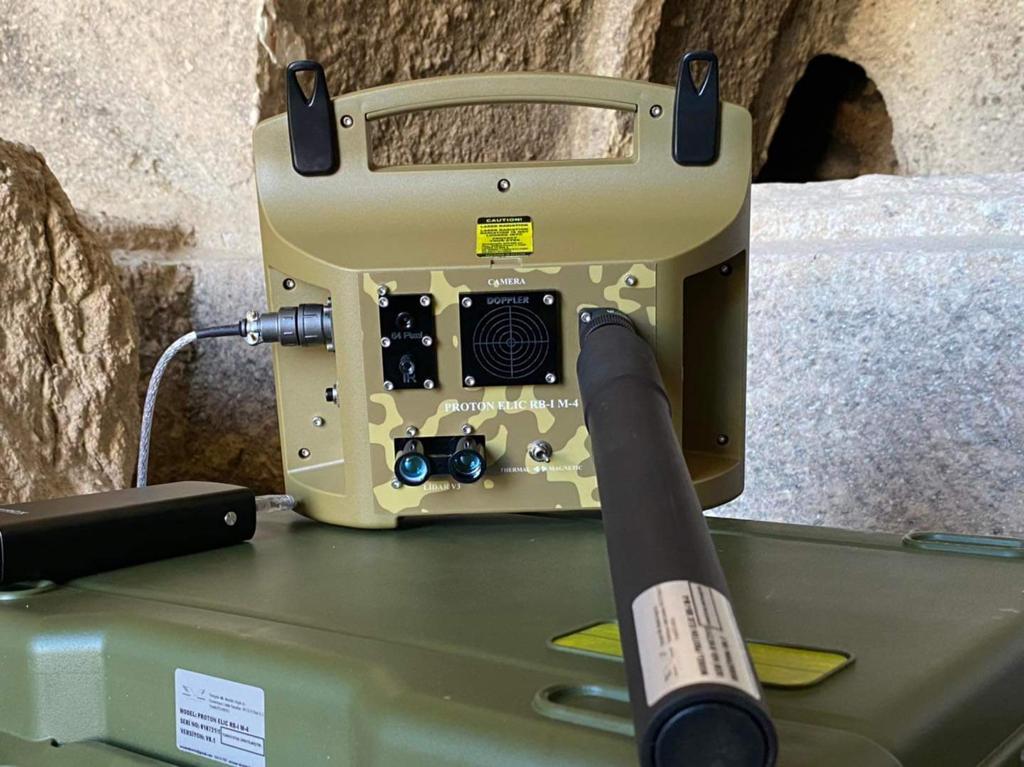
M-4 Professional underground imaging device domestic and national world’s latest technology digital sensor device all developed and facilitated by our company Assuva defense industry senior engineers. Command screen, High solution, 64 PXS Digital Thermal sensor, Three-axis magnetic. Digital sensor, adjustable axes, Personal sensitivity settings robust and lightweight body easy portable box design.
LET’S BRIEFLY INTRODUCE THE DEVICE:
M-4 Device has a completely digital sensor. The device magnetic sensor consists of three axes (X Y Z) axes automatically scan on the other hand, the rear command screen of the device is used when visual touch is desired.
For example; single-way (Z) axis scanning or scanning can be done by adjusting different axes such as (X,Y). This scanning device can be seen the command signal intensity on the back and has a rising and falling signal OSCILLATOR. It rises upwards in metallic objects and is represented by red color, this situation processes the fluent instant signal.
Dark blue aciculator also descends down to formations such as light blue spaces (Room, Tunnel, Passage) on a wide ground or a void.
On the other hand, this scanning process and all of these processes can be seen from the command screen without a PC connection. Processed data can be seen when the PC is connected.
Thermal sensor has 64 PXS feature and digital processed data visual and definition is very high.
In this scanning format, the device’s rear command back full screen 64 PXS offers the opportunity to see each point live with high resolution on the screen at equal height.
When these scans are requested, a processed data can be seen in 3D with PC connectivity, the data received on the command screen and the PC may differ by (1.2) units in terms of values. However, the ground difference of the scan will be seen with a full measurement value, and it will be very normal for thermal mode scanning detection in night scans and in elements such as wet ground, snowy ground, bumpy ground.
Moreover, both sensor sensitivities can be assigned to the desired level of increase and decrease on the device’s own command screen. And in a very dirty area, for example; when scanning in areas with waste metals, a comfortable and smooth image can be obtained. And many more personalized.
Areas of use:
Museum and geoarchaeological research ground preliminary definition works
Astronomy institutes meteorologists
Universities schools earth science departments
Underwater material and imaging
Institutions and organizations such as AFAD, UMKE search and rescue and post-earthquake detection of living beings
Hobby or professional treasure and archaeological research
Municipalities pipe, large water leakage detection, ground definition before underground excavation and lost pipe manhole detection
NATO pipeline protection institutions or organizations (illegal pipe traction lines detection)
And it is suitable for use in every possible anomaly detection regarding soil or underwater.
Technical specifications:
-Radar: Micro wave doppler radar
-Frequency: 433 Mhz
-Scanning frequency: max 5 Ghz
-Laser: 1pps
-Digital sensor scanning: 64 PXS
-Magnetic sensor: 3 axis
-Max depth: 50 mt
-Max scanning range: 1000 mt
-Working temperature: -20 degrees & +40 degrees
-Good usage result: 95%
-Software presentation type: 3D&3D transfer with 4D ( DAT ) CVS
-Battery time: 20,000 MLamp 30&50 hours may vary in weather conditions
–Warranty period: 2 years
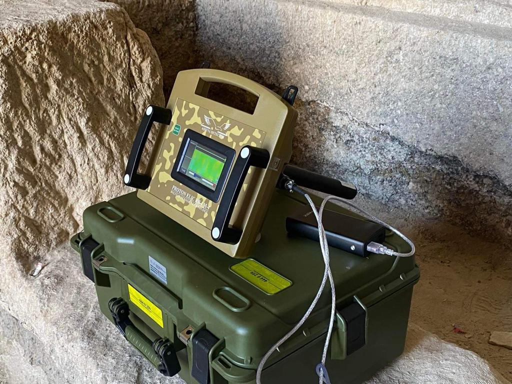
Scope of delivery:
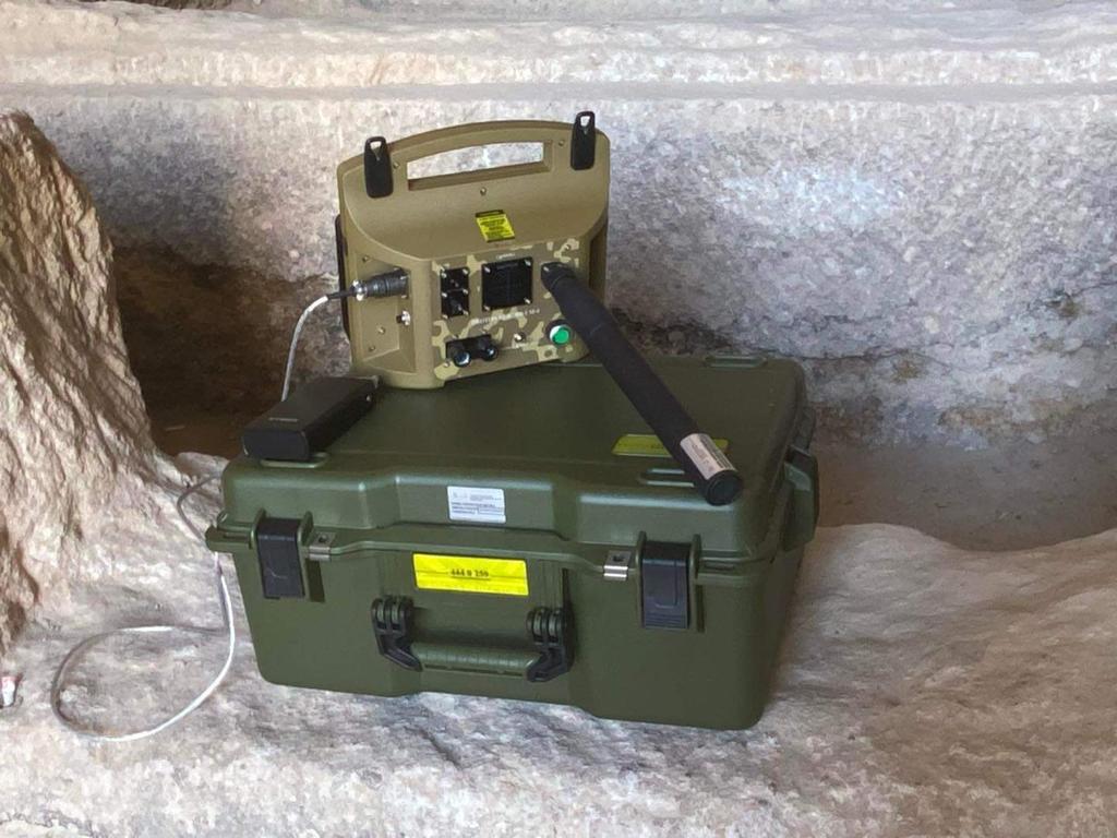
Carrying bag in black G SHOK waterproof
Backpack MIL TEC
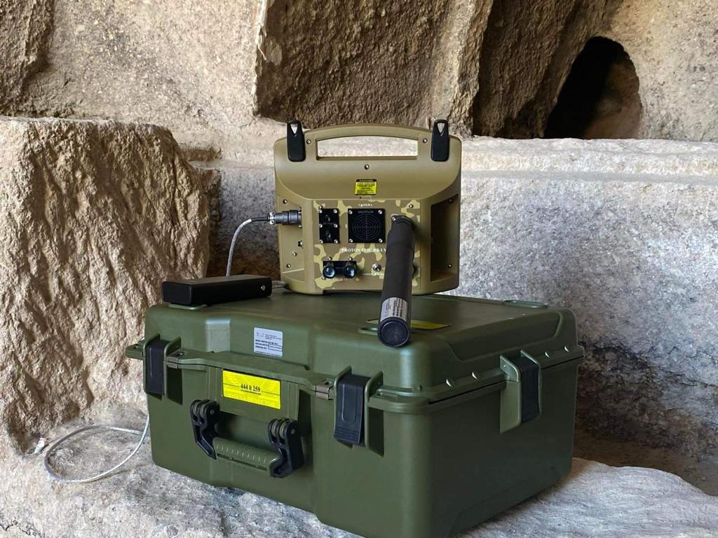
Device main unit
Prop sensor
Power cable
Power bank
Charging adapter
Neck strap
User manual
User CD
Note-Computer is not included.
Compatible Computer windows 10
Optional accessory:
-GPS antenna
-Custom production principles
-Box type and shape differences
Documents it has:
1-) NATO Stock Code-(NCAGE-TH763)
2-) World Standards (CE) Certificate
3-) ISO 9001 Quality Certificate
4-) ISO 14001 Quality Certificate
5-) ISO 22000 Quality Certificate
6-) ISO 45001 Quality Certificate
7-) ISO 27001 Quality Certificate
😎 ISO 10002 Quality Certificate
9-) ISO 18001 Quality Certificate
10-) OHSAS 18001 Quality Assurance Certificate
Device Fast Recognition Possibility Ability Technical Information Purpose
Thermal sensor-) It is a 4 line 16 column 64 PXS thermal camera. It can see thermal differences in the angle it looks at with 64 PXS resolution, the viewing angle is 60 degrees
Magnetic sensor-) The magnetic sensor measures the DC magnetic field intensity at its location, having 64 pieces allows faster data collection by measuring the magnetic field at 64 different points at the same time.
The system can be selected as either thermal or magnetic, and after collecting data from all sensors, it sends the data to the computer software via BLUETOOTH with the direction it looks.
The camera, which is at the center of a sphere in the computer environment, paints the inner surface of the sphere’s shell in the relevant colors, and the image is formed as the color correspondence of the thermal or magnetic field intensity in the direction it is looked at.
The PROTON ELIC RB-I device detects the target (thermal and magnetic) remotely through its sensors, instantly reflects its depth and location to the operator on the computer screen, and on the other hand, it provides detailed information about the target and the type of metal. The device quickly detects formations such as rooms, tunnels, passages, shelters, buried ammunition, vital materials, as well as detecting an element hidden behind trees or under snow with its thermal sensors.
This data presentation is very easy to use and understand thanks to its 3D visual special software. The user can receive instant data presentation with the start-stop command, and all commands and software have a Turkish menu.
When desired, this data can be instantly recorded on the map and GPS. The software is adapted for this situation.
The device can be used by a single person alone.
Specification:
Technical Field: It is related to the three-dimensional panoramic display device operating system that can receive 360-degree images and data records obtained by combining any desired sensor with the IMU sensor.
System Infrastructure: Today, technology is developing and updated every day. Three-dimensional (3D) image formation is also one of the developing technologies. While it is easy to perceive the width and height ratios of an object with the eye, it is not possible to perceive the depth of the same object. Separate images are provided for the right and left eyes, and a three-dimensional image is formed by the combination of these two images in the brain. 3D photo or film cameras also function in a similar way and record using a recording technique. In other words, they capture the image from a separate lens and record it.
Today, two cameras used for 3D film shooting focus on the same point by calculating the viewing angles, and it is desired that the focused cameras are recorded moving on the same path at the same time. It is possible to obtain three-dimensional images with cameras moving on different paths and times. For this reason, the cameras are fixed in order to eliminate unwanted movements and differences.
Description:
THREE-DIMENSIONAL PANORAMIC DISPLAY DEVICE AND OPERATION SYSTEM 5 Technical Field The invention is related to a three-dimensional panoramic display device and operation system that can record 360-degree images and data, obtained by combining any desired sensor with an IMU sensor. 10 Infrastructure of the Invention Today, technology is developing and updating every passing day. Three-dimensional (3D) image formation is also one of the developing technologies. While it is easy to perceive the width and height ratios of an object with the eye, it is not possible to perceive the depth of the same object. Separate images are provided for the right and left eyes, and a three-dimensional image is formed by combining these two images in the brain. 3D photo or film cameras also function in a similar way and record using a recording technique. In other words, they capture the image from two separate lenses and record it. 20 Today, the two cameras used for 3D film shooting focus on the same point by calculating the viewing angles, and it is desired that the focused cameras are recorded moving at the same time and on the same path. It is not possible to obtain three-dimensional images with cameras that move at different times and paths. For this reason, cameras are fixed to each other 25 to eliminate unwanted movements and differences. One of the images that can be adapted to a three-dimensional model is the panorama. Panorama allows multiple images taken from different angles to be combined into a single wide-angle image. Panoramic cameras can obtain both 180-degree and 360-degree panoramic images using one or more 30 lenses. The sound and images obtained with the panoramic camera are recorded in the data recording medium. The image data measured or recorded by image processing is transferred from one electronic medium to another electronic medium with the help of a computer and software and made readable on the device. In the known state of the technique, three 5-dimensional images can be obtained by combining two-dimensional (x and y axis) data and the data coming from only one sensor can be recorded at the same time. In the current technique, data is collected and visualized by sampling method by keeping it fixed to the ground. Positioning is done either manually or by using positioning satellites such as GPS. The user obtains visual data by visiting almost every point of the field where he/she will conduct research and collecting 10 samples. Today, sensors that act as a bridge by connecting the physical environment and electronic devices vary according to the input sizes of the variables. The values of these variables such as temperature, pressure, wavelength, current, concentration and permeability are measured by mechanical, thermal, electrical, magnetic, radiation and chemical sensors and converted into electrical signals. Sensors are grouped in two groups according to their feeding methods as passive sensors and active sensors. While passive sensors measure the signals they receive from their environment, active sensors produce their own signals and measure the interactions of this signal with the external environment and require more energy since they emit their own signals. Active sensors also provide analog or digital signal output according to the type of signal they produce. Analog sensors are converted into digital signals using (A/D) analog25 digital converters before the signal is directed to the microcontrollers. In digital sensors, there is no variability in the input and output values as in analog sensors and they produce discrete signals. The invention, three-dimensional panoramic display device and operating system; sends the signal to the microcontroller with analog sensors or digital sensors as in the state of the art 30, but unlike the state of the art, it can combine the information sent to the microcontroller with IMU (Inertial Measurement Unit) 2 and record 360-degree images and data in a three-dimensional panoramic manner. The invention, three-dimensional panoramic display device and operating system communicates with the main unit 5 via USB, Bluetooth or Wi-Fi thanks to this recording program. The main unit sends the data coming from the sensors connected to it to the program with the 3-dimensional 360-degree stance angle obtained from the IMU sensor. It reflects a viewing angle looking from the center of a sphere to the inner wall of the sphere on the screen. It can be opened in a computer environment with this program and with this recording transferred to the computer environment, the 360-degree anomaly differences of the shooting point can be examined panoramically by looking from the inside of a sphere to the inner shell of the sphere at 10 desired angles. This perspective calculates the angle of repose from the quaternion data coming from the IMU sensor. According to the obtained angle of repose, the relevant area of the inner wall of the sphere is painted in the relevant color according to the intensity of the data coming from the sensor. After a certain scan, the visual counterpart of the signal intensity obtained with the program will start to form on the inner wall of the sphere. The effect of visual shapes has been increased with various signal processing and interpolation algorithms. Thus, distinct images are obtained even at low signal levels 20. The structural and characteristic features of the invention and all its advantages will be understood more clearly thanks to the figures given below and the detailed explanation written by making references to these figures, and therefore this evaluation should be made by taking these figures and the detailed explanation into consideration. 25 Figures Helping to Explain the Invention Figure 1: Schematic representation of the operating system of the three-dimensional panoramic display device References Helping to Explain the Invention 30 1. Microcontroller 3 2. IMU sensor 3. Digital sensors 4. Analog sensors 5. Control buttons 5 6. LCD panel 7. Wireless module 8. Computer a. Transmitting the signal from the digital sensors to the microcontroller via the digital communication line 10 b. Transmitting the signal from the microcontroller to the computer via the wired communication line c. Transmitting the signal from analog sensors to the microcontroller via analog communication line d. Transmitting the signal from the microcontroller to 15 wireless modules via wireless communication line Disclosure of the Invention The invention relates to 20 three-dimensional panoramic display devices and operating systems consisting of microcontroller (1), IMU sensor (2), digital sensors (3), analog sensors (4), control buttons (5), LCD panel (6) and wireless module (7) sections. The invention in question, the three-dimensional panoramic display device; microcontroller (1) that controls the entire system and combines the information it receives from the sensors with the IMU sensor (2), IMU sensor (2) that detects motion in three-dimensional space and directs it 360 degrees, 25 digital sensors (3) that provide digital communication, analog sensors (4) that provide analog communication, control buttons (5) consisting of keypads that allow the user to control the device, LCD panel (6) that displays the menu and instantly received data by enabling the adjustments of the device and wireless module (7) that provides wireless communication with the computer (8) sections are integrated into each other. The process steps of the operating system of the three-dimensional panoramic display device, which is the subject of the invention, are as follows: 4 • Transmission of the signal coming from the digital sensors (3), which consist of acceleration, gyro and compass sensors in the IMU sensor and sensitive thermal and magnetic sensors operating as sensors and communicate with the microcontroller 5 in the control unit via the digital sensors I2C and SPI interfaces, to the microcontroller (1) via the digital communication line (a), • Transmission of the signal coming from the microcontroller (1) to the computer (8) via the wired communication line (b), • Transmission of the signal coming from the analog sensors (4), which consist of sensitive thermal and magnetic sensors and are read by the internal 10 16Bit ADC of the microcontroller, to the microcontroller (1) via the analog communication line (c), • Transmission of the signal coming from the microcontroller (1), which can communicate with the program wirelessly via USB or wirelessly via Bluetooth or Wifi, to the wireless module (7) via the wireless communication line (d). 15 The invention in question can also work with three-dimensional panoramic display device and operating system thermal and magnetic sensors. Thus, thermal detection of the image to be recorded is also provided. 20 The invention can record 360-degree images and data in three-dimensional panoramic display device and operating system by combining the information sent to the microcontroller (1) with the IMU sensor (2) and can also keep this record in its own memory. The recording with the three-dimensional panoramic display device and operating system can be opened in the computer (8) environment with the program. 25 With this record transferred to the computer (8), by looking at the inner shell of a sphere from the inside of the sphere at the desired angle, the 360-degree anomaly differences of the shooting point can be examined panoramically. Magnetic, electromagnetic, thermal or optical sensors can be used as measurement sensors in the device of the invention. The magnetic sensor is a sensor with a sensitivity of 30 1V/50uT working in the fluxgate technique coded TT-140. It gives the magnetic field intensity to the system as a voltage output in the range of 0-5V. 5 The invention in question receives the angle of stance from the IMU sensor with the main unit I2C protocol. It also receives the magnetic field strength value measured from the magnetic sensor with 16bit ADC. It combines these two data panoramically and sends the obtained data to the computer in real time via Bluetooth or any desired interface. 5 Three-dimensional panoramic display device and operating system, the computer program visualizes the data it receives in a way that the user can understand by coloring it according to the relevant angle of stance. The program visualizes the inside of a sphere’s shell as a camera looking from the center of the sphere. The received angle of stance and magnetic field strength are painted according to the relevant angle and strength of the sphere’s shell. The user paints the shell by taking measurements from 10 different angles as much as possible. Thus, over time, if a magnetic sensor is used, a magnetic projection is formed inside the sphere’s shell, and if a thermal sensor is used, a thermal projection is formed. This invention will allow the user to collect data from that point in 3 axes and 360 degrees of stance angle without leaving the point he is at with this technique. This process can be likened to 3 15-axis cameras. There are cameras looking at multiple different directions in these cameras. The data obtained from these cameras without changing their angles are combined to obtain 360-degree viewing angles in all 3 axes. The sensor used searches for a 1-pixel color according to the angle of the position. The user obtains a 360-degree image in 3 axes by turning around and collecting data and painting the sphere 20 in which he is located. The technique and all other features mentioned in each claim are followed by a reference number, and these reference numbers are used only to facilitate understanding of the claims, so it should not be considered that they limit the scope of any of the process steps indicated by these reference numbers for exemplification purposes. It is clear that a person skilled in the art can also reveal the innovation presented in the invention by using similar structures and/or apply this structure to other areas with similar purposes used in the relevant technique. Therefore, it is also obvious that such 30 structures will lack the criteria of innovation and especially surpassing the known state of the art. 6. CLAIMS 1. The invention is related to a three-dimensional panoramic display device and operating system that gives the magnetic field intensity to the system as a voltage output of 5 in the range of 0-5V with a magnetic sensor with a sensitivity of 1V/50uT operating in the fluxgate technique coded TT-140, and its feature is characterized by the integration of the following parts; IMU sensor (2) that receives the magnetic field intensity value measured from the magnetic sensor with 16bit ADC and the angle of stance with the main unit I2C protocol by controlling the entire system and the microcontroller (1) obtained by combining these two data panoramically, IMU sensor (2) that sends the data to the computer in real time via Bluetooth 10 or any desired interface, digital sensors (3) that provide digital communication, analog sensors (4) that provide analog communication, control buttons (5) consisting of keypads that allow the user to control the device, LCD panel (6) that displays the menu and instantaneous received data by enabling the adjustments of the device and wireless module (7) that provides communication with the computer (8) wirelessly. 2. It relates to the three-dimensional panoramic display device and its operating system according to claim 1, and its feature is; The three-dimensional panoramic display device to which both digital and analog sensors can be connected is characterized by comprising the following process steps of its operating system: • Transmission of the signal coming from the digital sensors (3), which consist of acceleration, gyro and compass sensors within the IMU sensor and sensitive thermal and magnetic sensors operating as sensors and which communicate with the 25 microcontroller in the control unit via I2C and SPI interfaces, to the microcontroller (1) via the digital communication line (a), • Transmission of the signal coming from the microcontroller (1) to the computer (8) via the wired communication line (b), • Transmission of the signal coming from the analog sensors (4), which consist of sensitive thermal and magnetic sensors and are read by the 30 internal 16Bit ADC of the microcontroller, to the microcontroller (1) via the analog communication line (c), 7 • Transmission of the signal coming from the microcontroller (1), which can communicate with the program wirelessly via USB or wirelessly via Bluetooth or Wifi, to the wireless module (7) via the wireless communication line.
Device Capabilities and Capabilities:
It has the ability to detect tunnel cave type formations (made by carving reinforced concrete-mesh wall-rock ground) buried underground with manual work or carved in natural ground.
It works flawlessly in all ground conditions (wet-snowy-icy-rocky-rugged-mineralized.) etc.
In addition to these capabilities, depth and distance detection are also available in the device software.